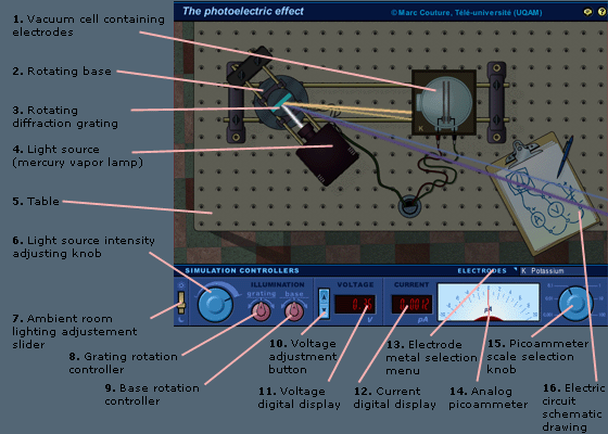
The main components of the apparatus are shown in Fig. 1
below (numbers in parentheses refer to numbers in the
figure)
a)
A table (5) with threaded holes allowing one to screw components on the surface.
b)
A variable intensity light source (4), i.e. a mercury vapor lamp with a collimated (nearly parallel) output beam.
c)
A diffraction grating (3) which, upon reflection, splits the white beam into multiple, single-color beams, one for every spectral line of the spectrum of mercury.
d)
A vacuum cell (1) containing two metal plates (or electrodes), the first one with a hole allowing the incoming light beam to strike the other. The electrodes are connected to two wires allowing one to put a voltage and to measure the current flowing between them. A schematic drawing of the circuit (16) is shown on the table.
e)
A distance-controlled supporting system (2) allowing one to rotate either only the grating (3) or both the lamp (4) and the grating.
The following figure shows the simulated apparatus as well
as the simulation controllers (bottow of the screen) which
allow one to modify the apparatus, ajust its parameters and
make measurements.

Figure 1 Screeshot of the simulated apparatus.
More precisely, lhe
controllers allow one to (left to right)
f)
Change the ambient room lighting (7). In the screenshot, the lighting has been reduced by about two thirds.
g)
Change the lamp intensity (6).
h)
Rotate either the grating only (8) or the base supporting both the grating and the lamb (9).
i)
Change the voltage (10) between the electrodes in the celle (voltage can be either positive or negative).
j)
Read, on a digital display (11), the value (in volts, V) of the voltage between the electrodes.
k)
Read, on a digital display (12), the value (in picoamperes, pA, i.e. 10-12 A ) if the current flowing between the electrodes.
l)
Measure the same quantity with a multiple-scale analog picoammeter (14); six different scales are available (15) with maximum deviation of the needle between 0,001 and 100 pA.
m)
Change the cell for another with electrodes made of a different metal. Four different metals are available (13).
Note that help bubbles (activated or deactivated by clicking
on the yellow button with a question mark, in the top right
corner of the screen) describe all the clickable objects
(buttons, menus) as well as some parts of the apparatus.
When activated, the bubbles appear when the cursor remains
over an object for a few seconds.
Marc Couture
July 9, 2008